Model selection of mold clamp
|
①
|
②
|
|
Capacity of Clamp:2-50(tons)
|
-
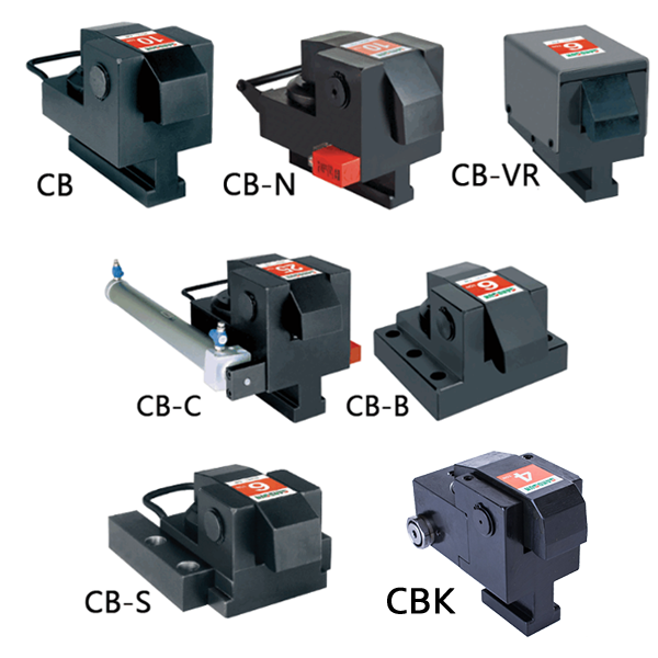
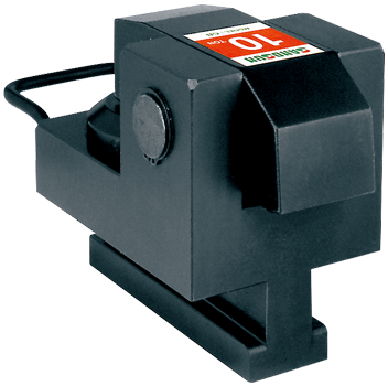
Empty:Standard type
-
S: Slide moveable type
-
N: With sensor type/DC10~30V (NPN, 3-Wire)
-
V: Heat-resistant type
-
C: Pneumatic cylinder movable type
-
VR: Heat-resistant with cover type
-
B: Fixed type
|
INSTRUCTION OF SPECIFICATION
Unit:mm
|
MODEL
|
CB-2
|
CB-4
|
CB-6
|
CB-10
|
CB-16
|
CB-25
|
CB-50
|
|
Capacity of Clamp/*tons
|
2
|
4
|
6
|
10
|
16
|
25
|
50
|
|
Total Stroke (X)/mm
|
8
|
8
|
8
|
8
|
8
|
8
|
10
|
|
Stroke of Clamp (Y)/mm
|
3
|
3
|
3
|
3
|
3
|
3
|
4
|
|
Preserved Stroke (Z)/mm
|
5
|
5
|
5
|
5
|
5
|
5
|
6
|
|
Total Volume/cc
|
7.5
|
13
|
21
|
38
|
55
|
98
|
220
|
|
The tolerance of template thinkness (H)
|
±2
|
±2
|
±2
|
±2
|
±2
|
±2
|
±2
|
*Hydraulic pressure: 250kgf/cm²
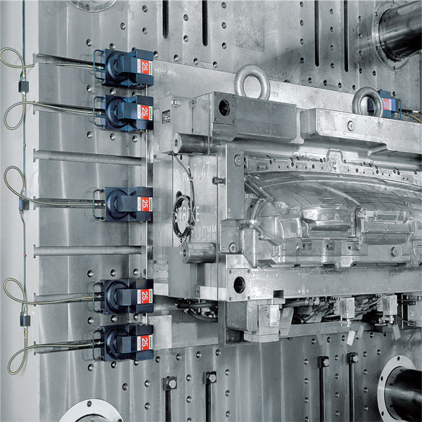
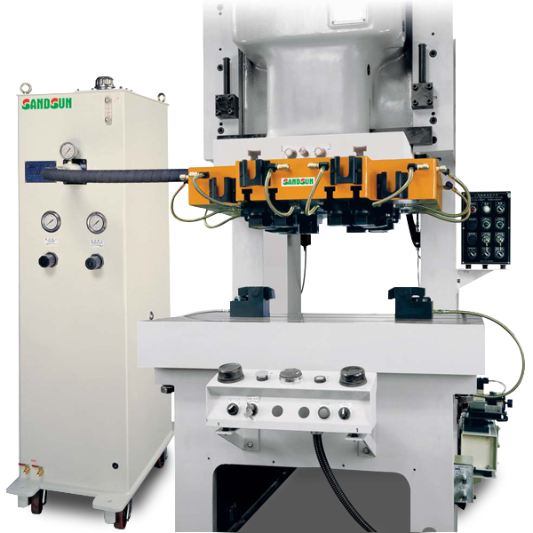
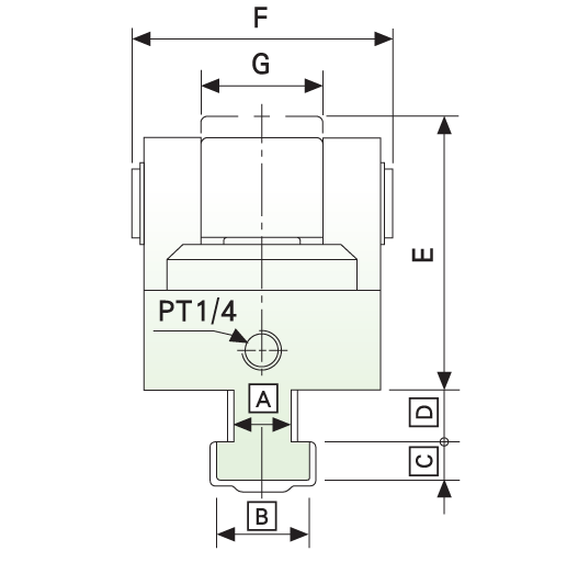
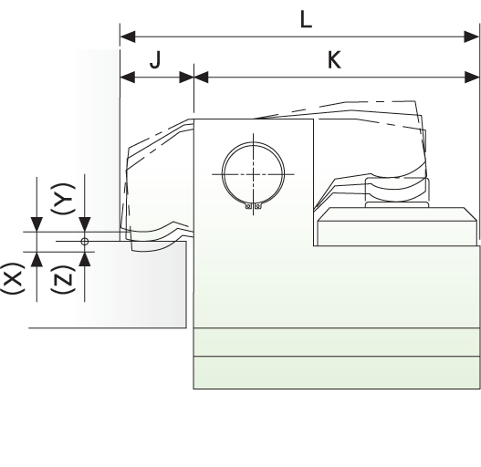
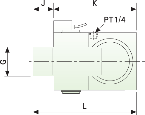
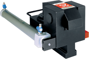
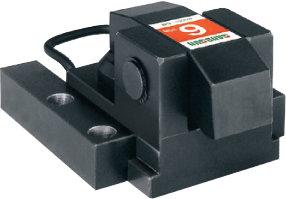
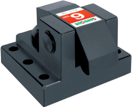
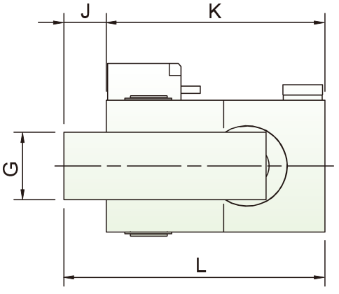
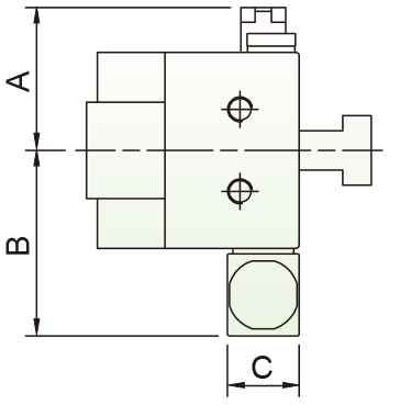
MODEL CB mould clamp
OUTLINE DIMENSIONS
Unit:mm
|
MODLE
|
|
CB-2
|
|
CB-4
|
|
CB-6
|
|
CB-10
|
|
CB-16
|
|
CB-25
|
|
CB-50
|
|
L
|
K
|
J
|
min. E
|
F
|
G
|
min.C
|
|
110
|
90
|
20
|
73
|
68
|
32
|
10
|
|
134
|
110
|
24
|
77
|
79
|
40
|
12
|
|
159
|
130
|
29
|
92
|
96
|
46
|
14
|
|
189
|
159
|
30
|
114
|
117
|
54
|
16
|
|
230
|
200
|
30
|
126
|
129
|
58
|
20
|
|
265
|
235
|
30
|
148
|
156
|
70
|
23
|
|
320
|
290
|
30
|
180
|
246
|
110
|
34
|
-
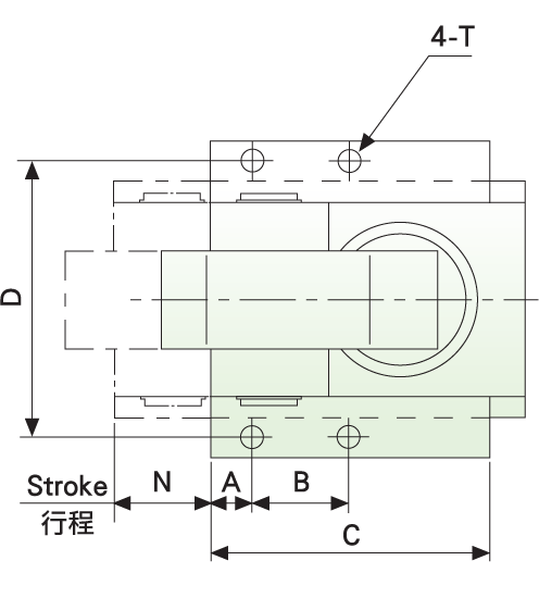
The size of clampsA B Cand D are made based on the size of T-slot.
VERTICAL LOADING
-
Platen with T-slot
-
Optional for position checking sensor
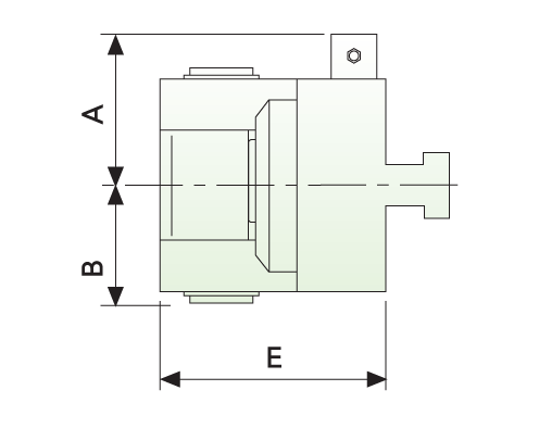
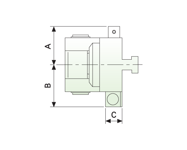
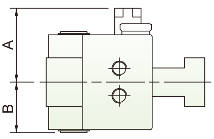
MODEL CB-N mould clamp
OUTLINE DIMENSIONS
Unit:mm
|
MODEL
|
|
CB-2N
|
|
CB-4N
|
|
CB-6N
|
|
CB-10N
|
|
CB-16N
|
|
CB-25N
|
|
CB-50N
|
|
A
|
B
|
min. E
|
G
|
J
|
K
|
L
|
|
56
|
34
|
73
|
32
|
20
|
90
|
110
|
|
61.5
|
39.5
|
77
|
40
|
24
|
110
|
134
|
|
70
|
48
|
92
|
46
|
29
|
130
|
159
|
|
80
|
58.5
|
114
|
54
|
30
|
159
|
189
|
|
86
|
64.5
|
126
|
58
|
30
|
200
|
230
|
|
99
|
78
|
148
|
70
|
30
|
235
|
265
|
|
145
|
123
|
180
|
110
|
30
|
290
|
320
|
VERTICAL LOADING
-
Platen with T-slot and manual clamp with sensor.
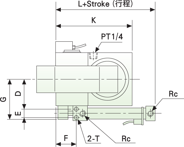
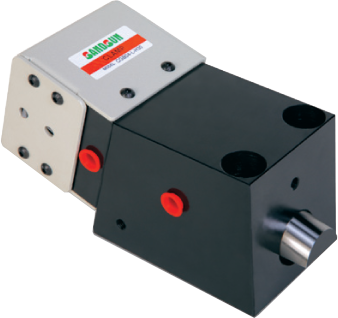
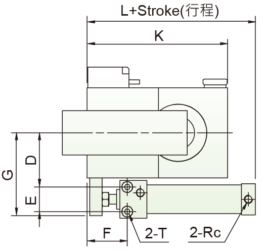
MODEL CB-C
OUTLINE DIMENSIONS
Unit:mm
|
MODEL
|
|
CB-2C
|
|
CB-4C
|
|
CB-6C
|
|
CB-10C
|
|
CB-16C
|
|
CB-25C
|
|
CB-50C
|
|
A
|
B
|
C
|
D
|
E
|
F
|
G
|
K
|
L
|
Rc
|
Tapping(T)
|
|
56
|
68
|
28
|
41
|
20
|
57.5
|
66
|
90
|
131
|
1/8
|
M6x12D
|
|
61.5
|
73.5
|
28
|
46.5
|
20
|
57.5
|
71.5
|
110
|
131
|
1/8
|
M6x12D
|
|
70
|
86
|
34
|
55
|
24
|
62.5
|
82
|
130
|
135
|
1/8
|
M6x12D
|
|
80
|
104
|
40
|
66
|
30
|
48.5
|
101
|
159
|
129
|
1/8
|
M8x16D
|
|
86
|
119.5
|
50
|
73.5
|
36
|
50
|
117
|
200
|
141
|
1/8
|
M10x20D
|
|
99
|
133
|
50
|
87
|
36
|
50
|
130
|
235
|
141
|
1/8
|
M10x20D
|
|
145
|
263
|
100
|
138
|
110
|
62
|
220
|
290
|
192
|
3/8
|
M16x32D
|
VERTICAL LOADING
-
Platen with T-slot and clamps moved automatically by pneumatic cylinder.
-
Another selection of clamping direction: left-right.
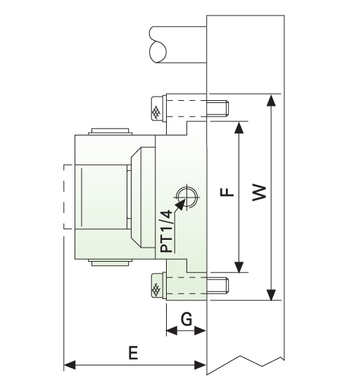
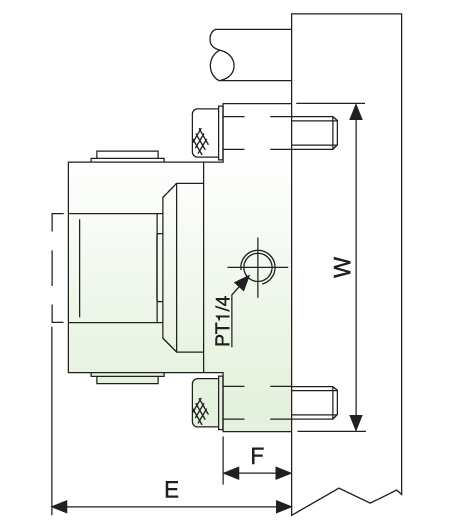
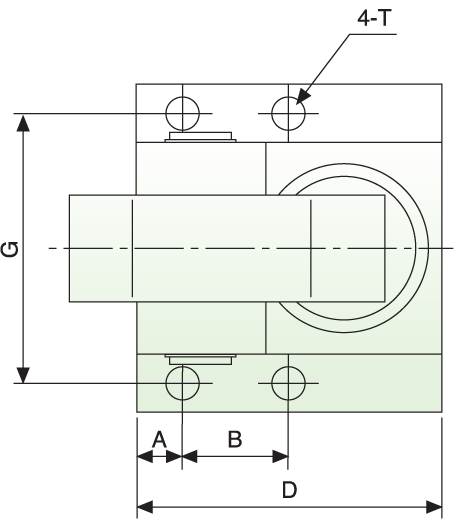
MODEL CB-S
OUTLINE DIMENSIONS
Unit:mm
|
MODEL
|
|
CB-2S
|
|
CB-4S
|
|
CB-6S
|
|
CB-10S
|
|
CB-16S
|
|
CB-25S
|
|
A
|
B
|
C
|
D
|
min.E
|
F
|
G
|
W
|
max. N
|
Tapping (T)
|
|
12
|
20
|
80
|
98
|
90
|
76
|
30
|
124
|
25
|
M10X20D
|
|
12
|
25
|
100
|
109
|
93
|
87
|
30
|
135
|
30
|
M12X24D
|
|
15
|
30
|
120
|
126
|
109
|
104
|
30
|
152
|
35
|
M12X24D
|
|
15
|
35
|
150
|
148
|
131
|
124
|
36
|
174
|
40
|
M14X28D
|
|
20
|
40
|
200
|
166
|
142
|
138
|
44
|
200
|
50
|
M18X36D
|
|
20
|
50
|
235
|
200
|
163
|
168
|
48
|
240
|
60
|
M22X45D
|
VERTICAL LOADING
-
For Platen without T-slots and the sizes of mold are variable.
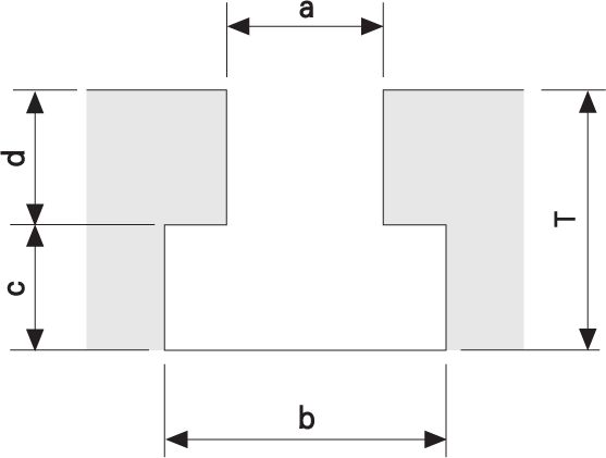
Suggested dimension of T-slot | Additional T-slots plated
|
MODEL
|
|
CB-2
|
|
CB-4
|
|
CB-6
|
|
CB-10
|
|
CB-16
|
|
CB-25
|
|
CB-50
|
|
T
|
a
|
b
|
c
|
d
|
|
32
|
18
|
32
|
14
|
18±0.2
|
|
40
|
22
|
37
|
16
|
24±0.2
|
|
40
|
22
|
37
|
16
|
24±0.2
|
|
44
|
28
|
48
|
18
|
26±0.2
|
|
52
|
28
|
48
|
22
|
30±0.2
|
|
61
|
36
|
56
|
25
|
36±0.2
|
|
84
|
48
|
80
|
36
|
48±0.2
|
-
T: The thickness of additional T-slot platen (min.)
MODEL CB-B
OUTLINE DIMENSIONS
Unit:mm
|
MODEL
|
|
CB-2B
|
|
CB-4B
|
|
CB-6B
|
|
CB-10B
|
|
CB-16B
|
|
CB-25B
|
|
A
|
B
|
D
|
F
|
G
|
min. E
|
W
|
Tapping (T)
|
|
12
|
35
|
90
|
20
|
84
|
90
|
106
|
M10X20D
|
|
12
|
40
|
110
|
25
|
95
|
93
|
117
|
M12X24D
|
|
15
|
45
|
130
|
30
|
115
|
109
|
140
|
M12X24D
|
|
15
|
55
|
159
|
30
|
135
|
131
|
160
|
M14X28D
|
|
20
|
65
|
200
|
30
|
158
|
142
|
192
|
M16X32D
|
|
20
|
80
|
235
|
30
|
184
|
163
|
218
|
M18X36D
|
VERTICAL LOADING
-
For Platen without T-slot and the sizes of mold is unified.
-
Suggest CB-S for movable platen.
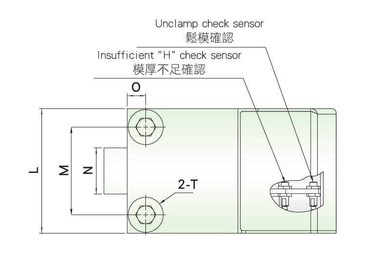
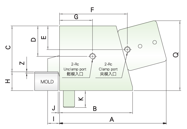
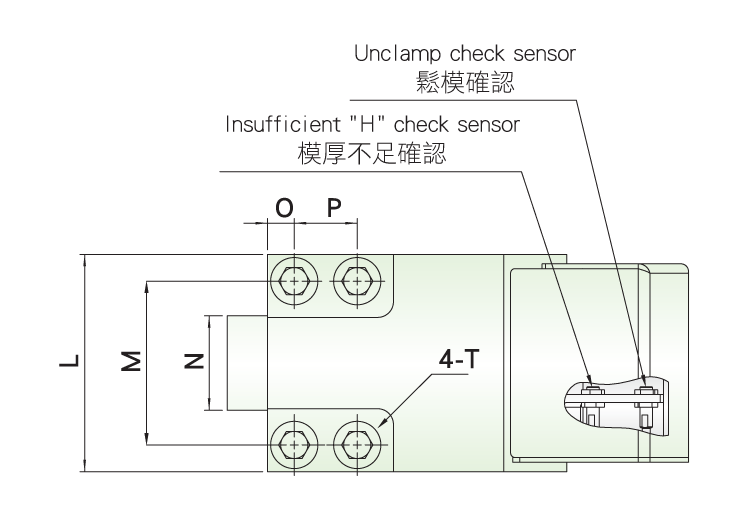
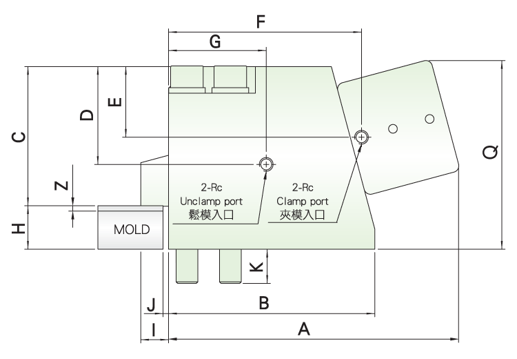
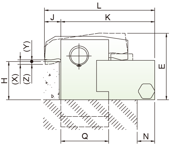
MODEL CG
-
CG Clamp is charactered in mechanical locking system.
The holder of clamp can be shrunk into the clamp when unclamping. It can avoid interference between the holder and mold template.
-
It is only applied on Mold Changer System.
Model Selection
|
①
|
②
|
③
|
④
|
|
The capacity of clamp (4~50 ton)
|
Thickness of template
( H±0.5mm )
|
The direction of piping and wiring connection:
L: on the left side (as below drawing)
R: on the right side
U: on the upper side
|
Sensor voltage:
3: DC10~30V (NPN, 3-Wire)
4: DC10~30V (PNP, 3-Wire)
|
INSTRUCTION OF SPECIFICATION
Unit:mm
|
MODEL
|
|
Clamping force /*tons
|
|
Retaining force /**tons
|
|
Preserved stroke (Z) /mm
|
|
Working temperature /℃
|
|
CG-4B
|
CG-6B
|
CG-10B
|
CG-16B
|
CG-25B
|
CG-50B
|
|
4
|
6
|
10
|
16
|
25
|
50
|
|
0.8
|
1.2
|
2
|
3.2
|
5
|
10
|
|
1.5
|
2
|
|
Max 70℃
|
* Hydraulic Pressure: 140kg/cm²
** No hydraulic pressure
Unit:mm
|
MODEL
|
|
CG-4B
|
|
CG-6B
|
|
CG-10B
|
|
CG-16B
|
|
CG-25B
|
|
CG-50B
|
|
A
|
B
|
C
|
D
|
E
|
F
|
G
|
I
|
J
|
K
|
L
|
M
|
N
|
O
|
P
|
Q
|
Rc
|
H±0.5
|
T
|
|
186
|
123
|
75
|
50
|
30
|
113
|
42
|
17
|
2
|
27
|
90
|
62
|
35
|
14
|
-
|
115
|
1/4
|
25
|
M16
|
|
202
|
140
|
85
|
48
|
36
|
126
|
48
|
19
|
3
|
33
|
110
|
76
|
45
|
17
|
-
|
124
|
1/4
|
30
|
M20
|
|
215
|
150
|
98
|
53
|
42
|
138
|
56
|
23
|
3
|
36
|
135
|
95
|
50
|
20
|
-
|
131
|
1/4
|
30
|
M24
|
|
258
|
190
|
128
|
74
|
53
|
175
|
82
|
28
|
5
|
33
|
138
|
104
|
60
|
17
|
40
|
156
|
1/4
|
30
|
M20
|
|
302
|
240
|
159
|
100
|
64
|
212
|
100
|
33
|
5
|
40
|
170
|
130
|
75
|
20
|
50
|
188
|
1/4
|
40
|
M24
|
|
365
|
290
|
195
|
140
|
88
|
268
|
125
|
35
|
5
|
50
|
215
|
162
|
100
|
27
|
60
|
227
|
3/8
|
50
|
M33
|
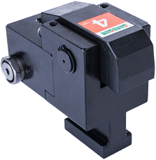
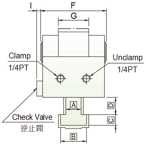
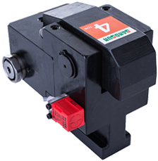
Check Valve Mold Clamp
FEATURE
-
Better safety design clamp.
-
Clamp with Build-in check valve, it can keeps the pressure itself.
-
The clamp will not release, even if the hydraulic tube is damaged.
-
Separate clamp body design, easy for maintain and exchange.
-
Waterproof design for cylinder and piston.
Model Selection
|
①
|
②
|
|
Capacity of Clamp:2-25(tons)
|
-
Empty:Standard type
-
N: With sensor type/DC10~30V (NPN, 3-Wire)
-
C: Pneumatic cylinder movable type
|
INSTRUCTION OF SPECIFICATION
Unit:mm
|
MODEL
|
|
Capacity of Clamp/*tons
|
|
Total Stroke (X)/mm
|
|
Stroke of Clamp (Y)/mm
|
|
Preserved Stroke (Z)/mm
|
|
Total Volume of cylinder/cc
|
|
The tolerance of the template thickness (H) /mm
|
|
CBK-2
|
CBK-4
|
CBK-6
|
CBK-10
|
CBK-16
|
CBK-25
|
|
2
|
4
|
6
|
10
|
16
|
25
|
|
8
|
8
|
8
|
8
|
8
|
8
|
|
3
|
3
|
3
|
3
|
3
|
3
|
|
5
|
5
|
5
|
5
|
5
|
5
|
|
8
|
13
|
22
|
38
|
55
|
99
|
|
±2
|
±2
|
±2
|
±2
|
±2
|
±2
|
*Hydraulic pressure: 24.5MPa (250kg/cm²)(3550psi)
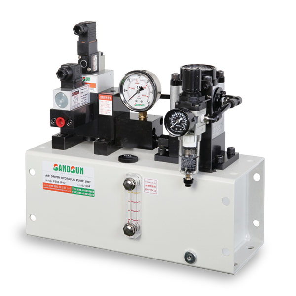
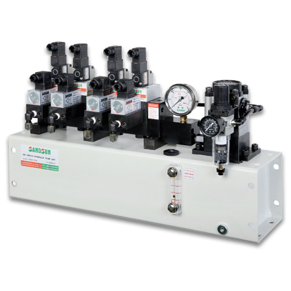
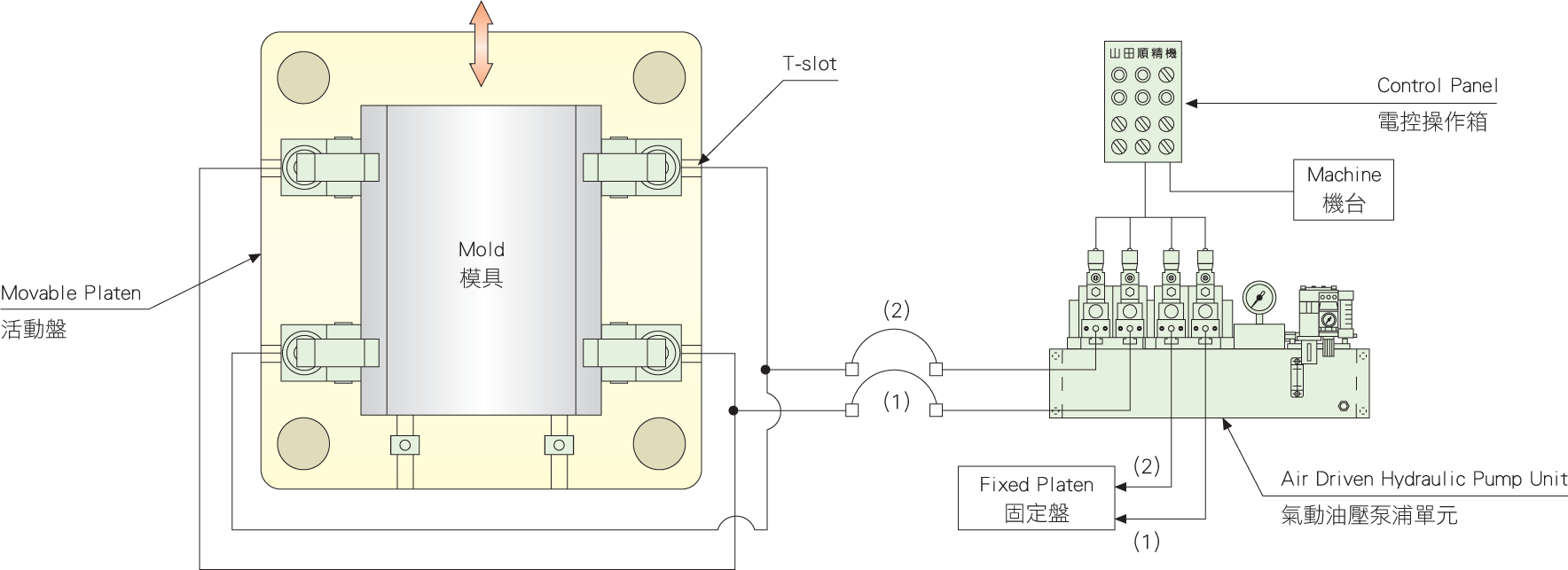
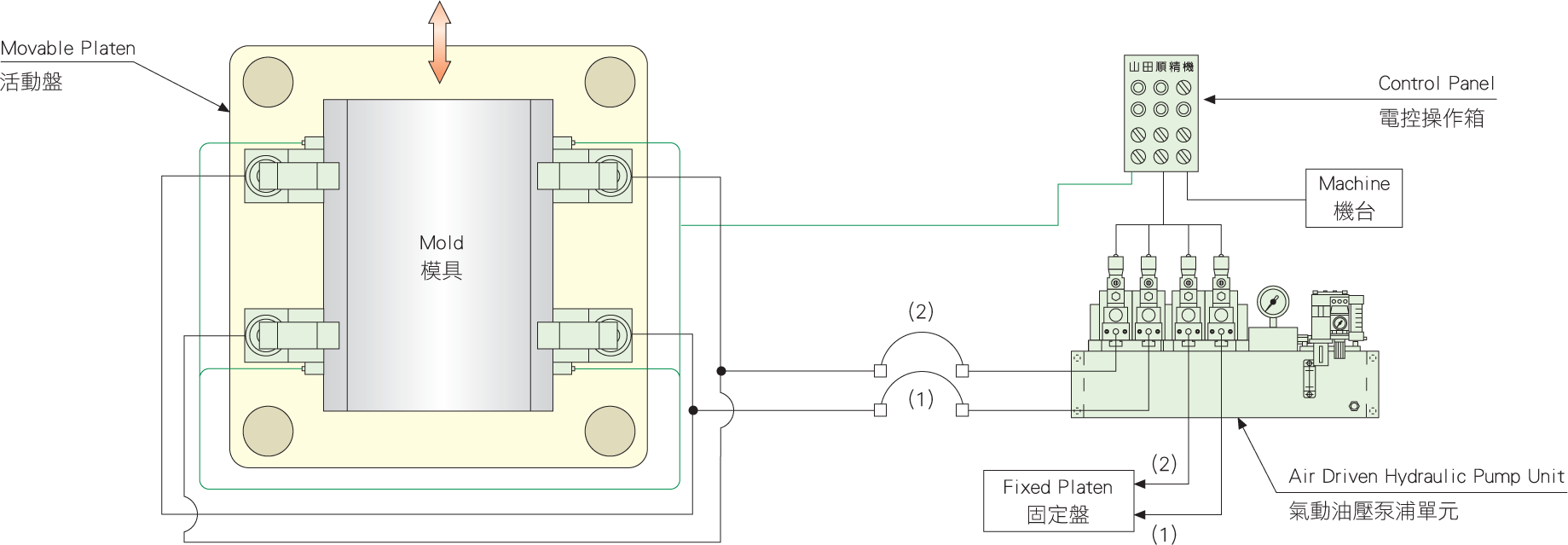
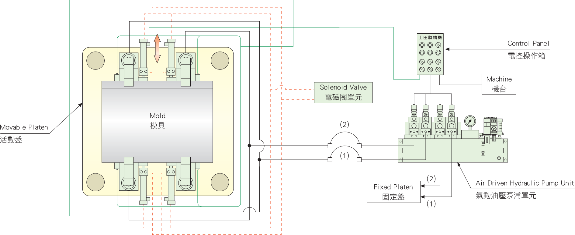
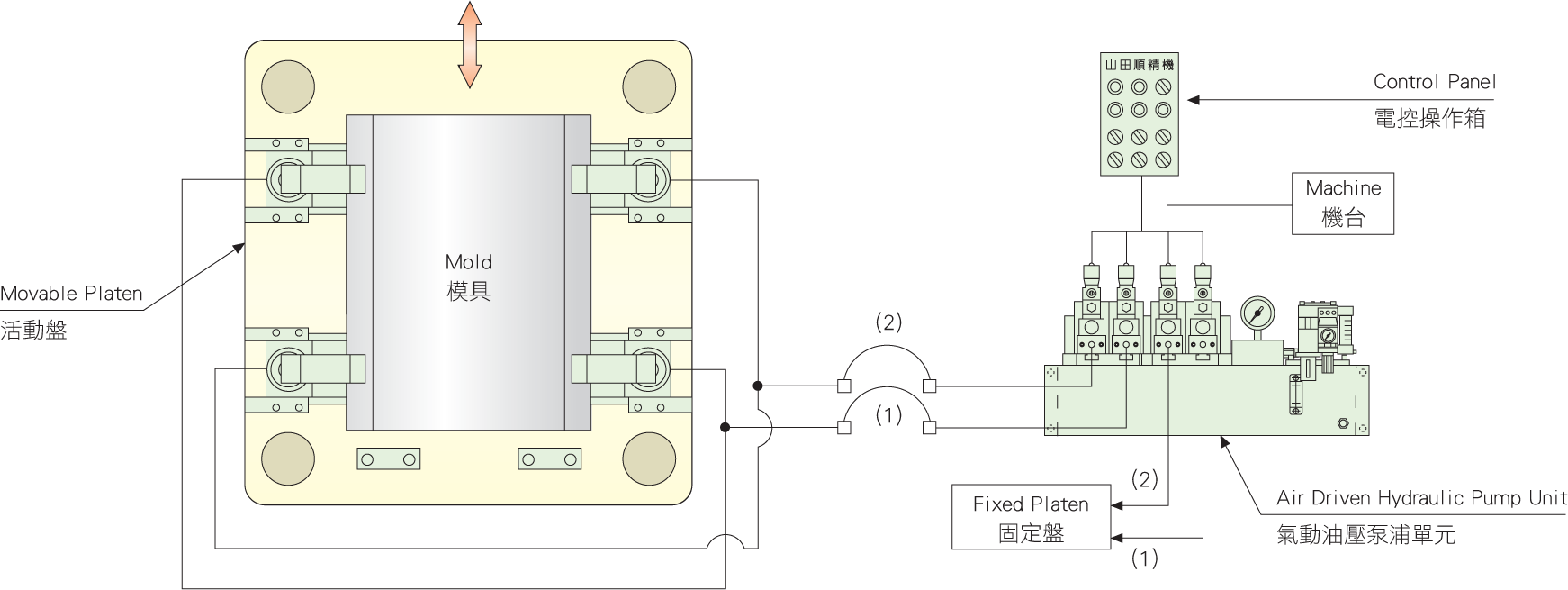
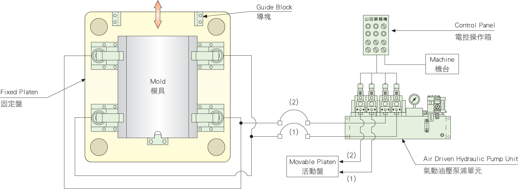
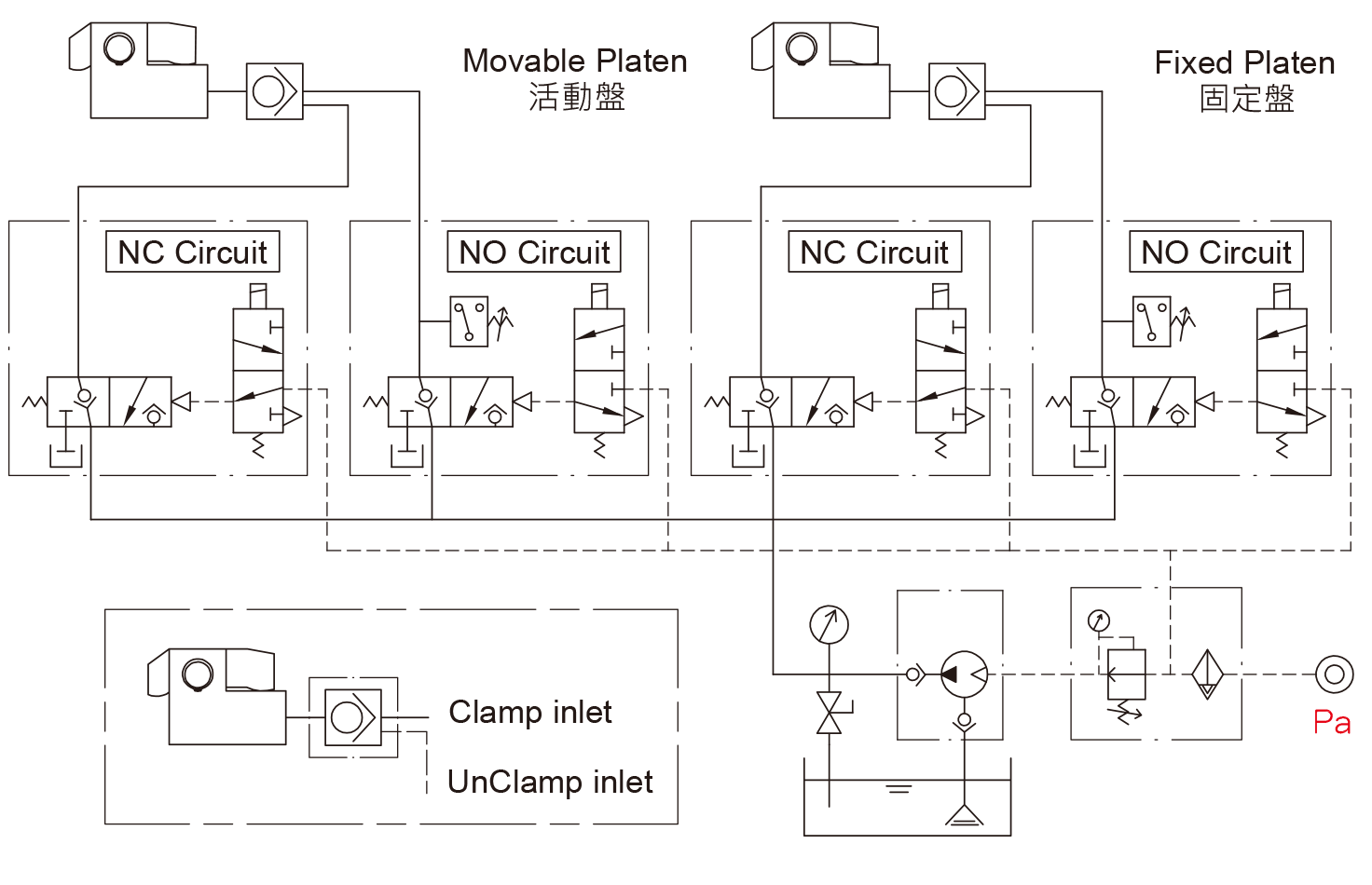
CIRCUIT CONTROL SYSTEM
MODEL CBK
OUTLINE DIMENSIONS
Unit:mm
|
MODEL
|
|
CBK-2
|
|
CBK-4
|
|
CBK-6
|
|
CBK-10
|
|
CBK-16
|
|
CBK-25
|
|
min.C
|
min.E
|
F
|
G
|
I
|
J
|
K
|
L
|
max. N
|
Q
|
|
10
|
73
|
68
|
32
|
9
|
20
|
106
|
126
|
15
|
46
|
|
12
|
85
|
79
|
40
|
9
|
24
|
124
|
148
|
20
|
61
|
|
14
|
100
|
96
|
46
|
9
|
29
|
149
|
178
|
25
|
80
|
|
16
|
119
|
117
|
54
|
8
|
30
|
171
|
201
|
30
|
87
|
|
20
|
133
|
129
|
58
|
8
|
30
|
202
|
232
|
35
|
108
|
|
23
|
150
|
156
|
70
|
8
|
30
|
235
|
265
|
40
|
128
|
MODEL CBK-N
OUTLINE DIMENSIONS
Unit:mm
|
MODEL
|
|
CBK-2N
|
|
CBK-4N
|
|
CBK-6N
|
|
CBK-10N
|
|
CBK-16N
|
|
CBK-25N
|
|
A
|
B
|
G
|
J
|
K
|
L
|
|
52
|
56
|
32
|
20
|
106
|
126
|
|
57.5
|
39.5
|
40
|
24
|
124
|
148
|
|
70
|
48
|
46
|
29
|
149
|
178
|
|
80
|
58.5
|
54
|
30
|
171
|
201
|
|
85.5
|
64.5
|
58
|
30
|
202
|
232
|
|
99
|
78
|
70
|
30
|
235
|
265
|
MODEL CBK-C
OUTLINE DIMENSIONS
Unit:mm
|
MODEL
|
|
CBK-4C
|
|
CBK-6C
|
|
CBK-10C
|
|
CBK-16C
|
|
CBK-25C
|
|
A
|
B
|
C
|
D
|
E
|
F
|
G
|
K
|
L
|
Rc
|
Tapping (T)
|
|
58
|
73.5
|
29
|
46.5
|
20
|
57.5
|
73.5
|
124
|
131
|
1/8
|
M6 X 12D
|
|
70
|
86
|
34.5
|
55
|
24
|
61.5
|
82
|
149
|
135.5
|
1/8
|
M6 X 12D
|
|
80
|
104
|
41.5
|
66
|
30
|
49
|
101
|
171
|
130
|
1/8
|
M8 X 16D
|
|
86
|
119.5
|
52
|
73.5
|
36
|
50
|
112.5
|
202
|
141
|
1/8
|
M10 X 20D
|
|
99
|
139
|
63.5
|
88
|
40
|
65
|
138.5
|
235
|
168
|
1/4
|
M10 X 20D
|